[DIAGRAM] Miata Hose Diagram
1970-81 Vacuum Diagrams Jump to Latest Follow 8K views 12 replies 3 participants last post by etimmscott Nov 1, 2017 firebird_madness Discussion starter 1682 posts · Joined 2009 #1 · May 14, 2013 (Edited by Moderator) 1970 6 Cyl Vacuum hose routing for the TCS system. 1970 V8 Vacuum hose & TCS routing. Attachments
[DIAGRAM] 2001 Chevy Blazer 43 Vacuum Line Diagram
A vacuum hose diagram or routing guide can be helpful in identifying the correct routing and size of vacuum hoses for specific vehicle models. Components of the Engine Vacuum Hose System Engine Vacuum Hose: Definition and Function The engine vacuum hose is an essential component of the engine vacuum hose system.
Vacuum Hose Diagram I Am Looking for a Vacuum Hose Diagram to See...
We will provide you with the basic free Vacuum diagrams in an email that can be viewed, saved or printed for future use. Basic Automotive Vacuum diagrams are available free for domestic and Asian vehicles. Some European Vacuum diagrams are available also. Once you get your Free Vacuum Diagrams, then what do you do with it.

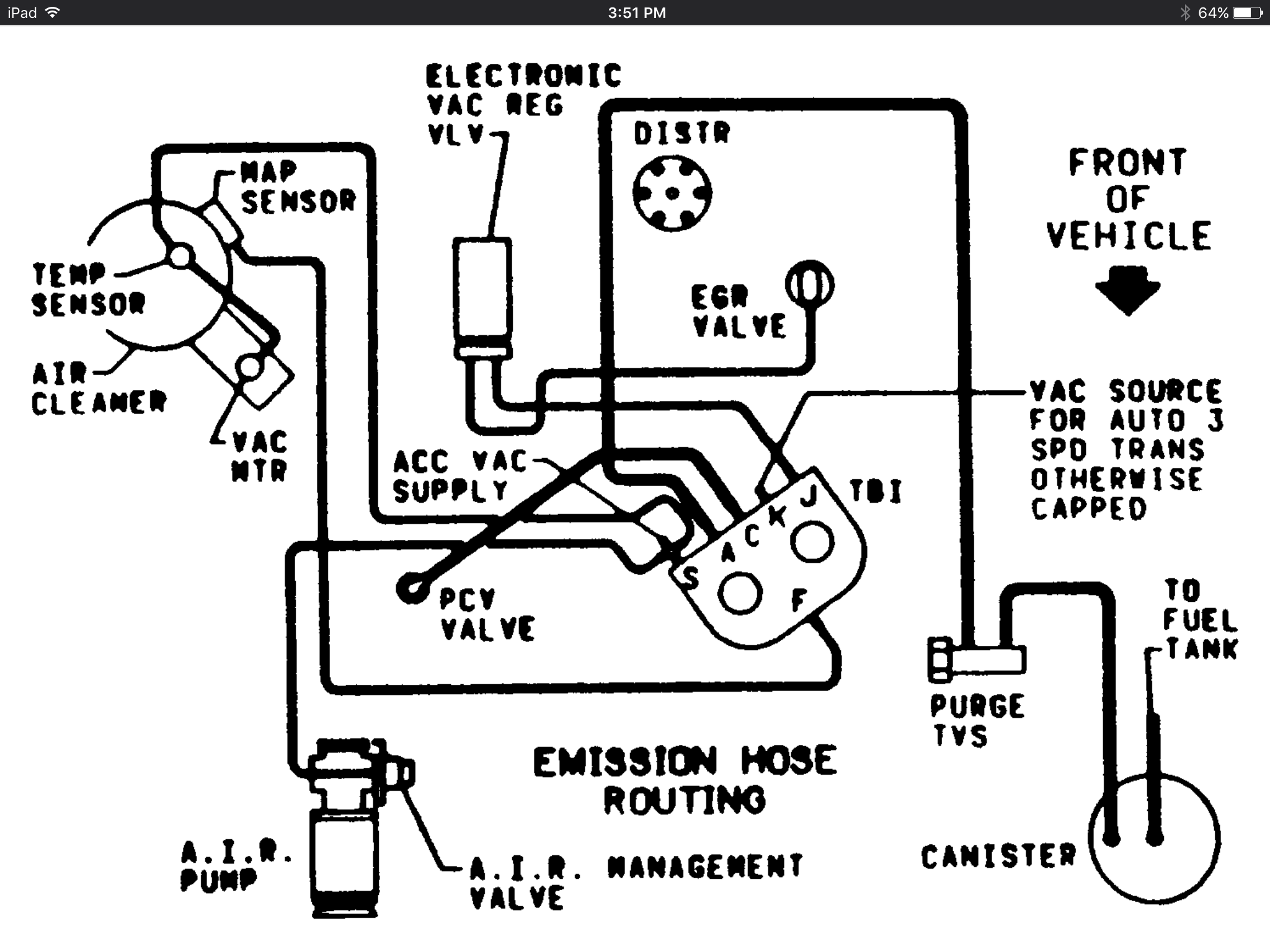
Need a vacuum hose routing diagram for a chevy s10 4.3L vortec engine
The vacuum hose diagram for a Jeep YJ provides a visual representation of how the hoses are routed in the vehicle. This diagram is crucial for troubleshooting and identifying any potential issues with the vacuum system. It helps owners and mechanics locate and inspect the hoses for leaks, cracks, or loose connections.
Vacuum Hose Routing Diagram I Need to Replace Crummbling Vaccum
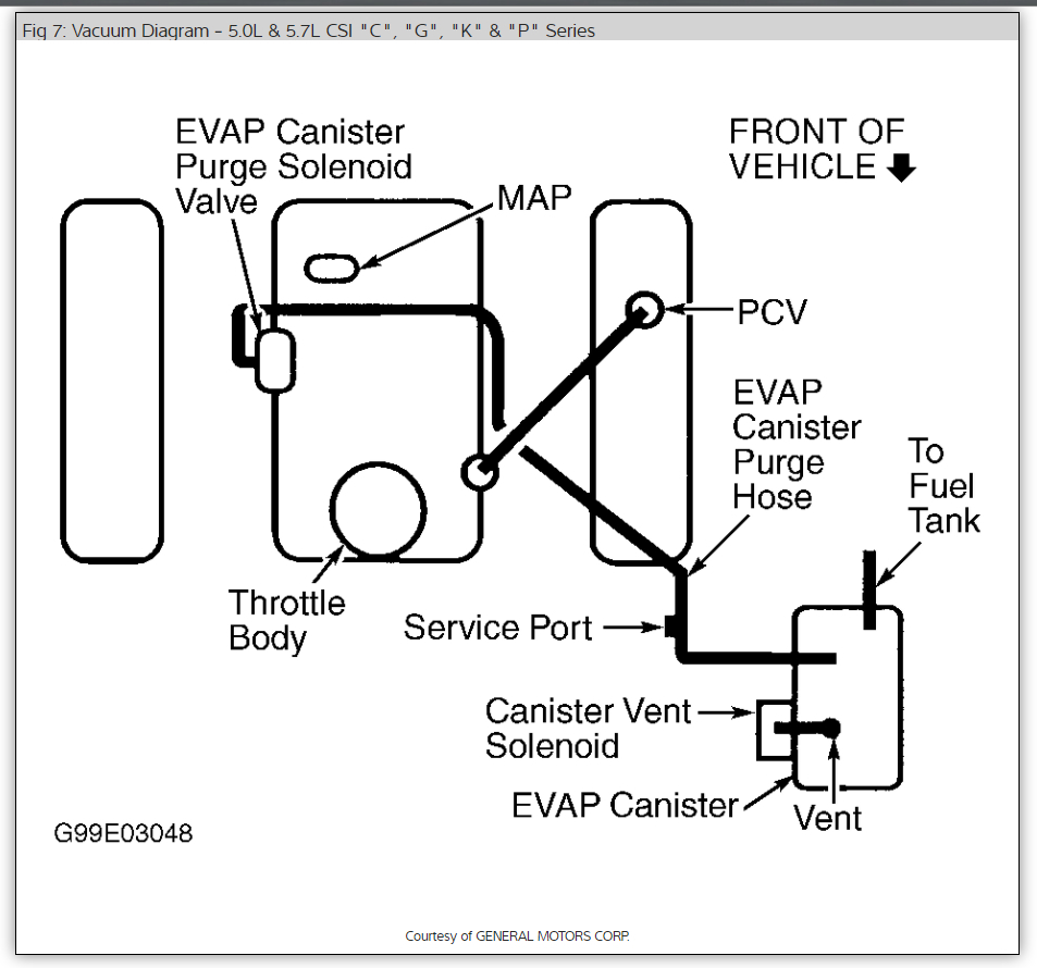
These diagrams include: Fig. 1: Vacuum hose schematic-1980. Fig. 2: Vacuum hose schematic-1980. Fig. 3: Vacuum hose schematic-1980. Fig. 4: Vacuum hose schematic-1980. Fig. 5: Vacuum hose schematic-1980. Fig. 6: Vacuum hose schematic-1980. Access our GM Full-Size Trucks 1980-1987 Vacuum Diagrams Repair Guide by creating an account or signing.
Vacuum Hose Routing Diagram I Need to Replace Crummbling Vaccum
Transmission Vacuum Hose Diagram. Robert. October 7, 2022. Transmission vacuum hoses help regulate the shifting of gears in an automatic transmission. These hoses are connected to various parts of the transmission, and they can become worn or damaged over time. It's important to know where each hose is located and what it does, so you can.

Vacuum Hose Diagrams 19942000 FWD Turbos
The vacuum hose diagram is a visual representation of the routing and connections of the vacuum hoses in the 5.4 Triton engine. It provides a clear and detailed guide to help mechanics and DIY enthusiasts understand how the vacuum system works and ensure proper installation and maintenance. Each line in the diagram represents a specific vacuum.

Vacuum Hose Diagrams 19942000 FWD Turbos
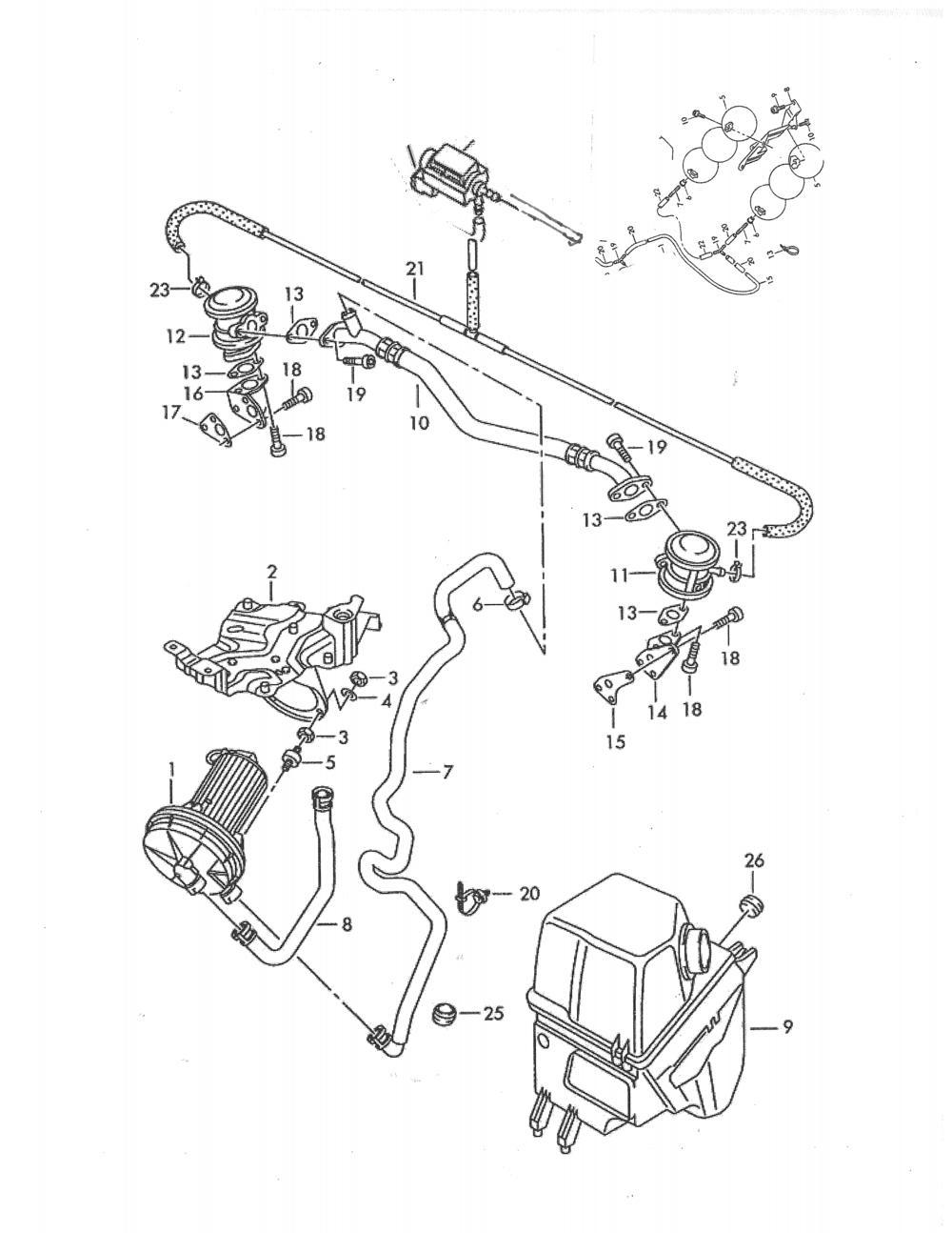
Vacuum Diagrams Master View: Legend: All measurements were taken with digital dial calipers rounded for best fit. Notes: * - Although VW says 3.5mm hose fits O, Q and T I think 4.5mm hose is a better fit especially at the pressure regulator. My bus has seen 18" of vacuum 236 ft. above sea level so I think it worked out. Close ups:
Nylon hose Vacuum line diagram for chevy 350
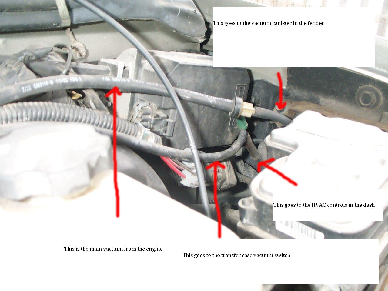
The vacuum hose diagram illustrates the various vacuum lines and connections in your vehicle's engine compartment. It provides a visual representation of how the vacuum system is laid out and how the different components are interconnected. By understanding this diagram, you will be able to identify and locate specific vacuum hoses, valves.
Vacuum Line Diagram exatin.info
Vacuum hose diagrams? Jump to Latest Follow 58K views 15 replies 6 participants last post by cocobolo95 Sep 28, 2020 W WARBIRD93 Discussion starter 165 posts · Joined 2008 #1 · Mar 27, 2009 anyone know where I can find the schematics to all the vacuum lines in the car? Thanks ahead of time. Reply Like Sort by Oldest first M monster81

258 vacuum hose question
Vacuum Hose Routing & Where To Get Diagrams. Find your vacuum diagram free at AUTOZONE.COM ; click on repair guides and then your yr, make, model info. They are still adding to that section, but it does hv diagrams for Ford Trucks. A couple questions for you motorheads. There are multiple diagrams for the same engine, same year.

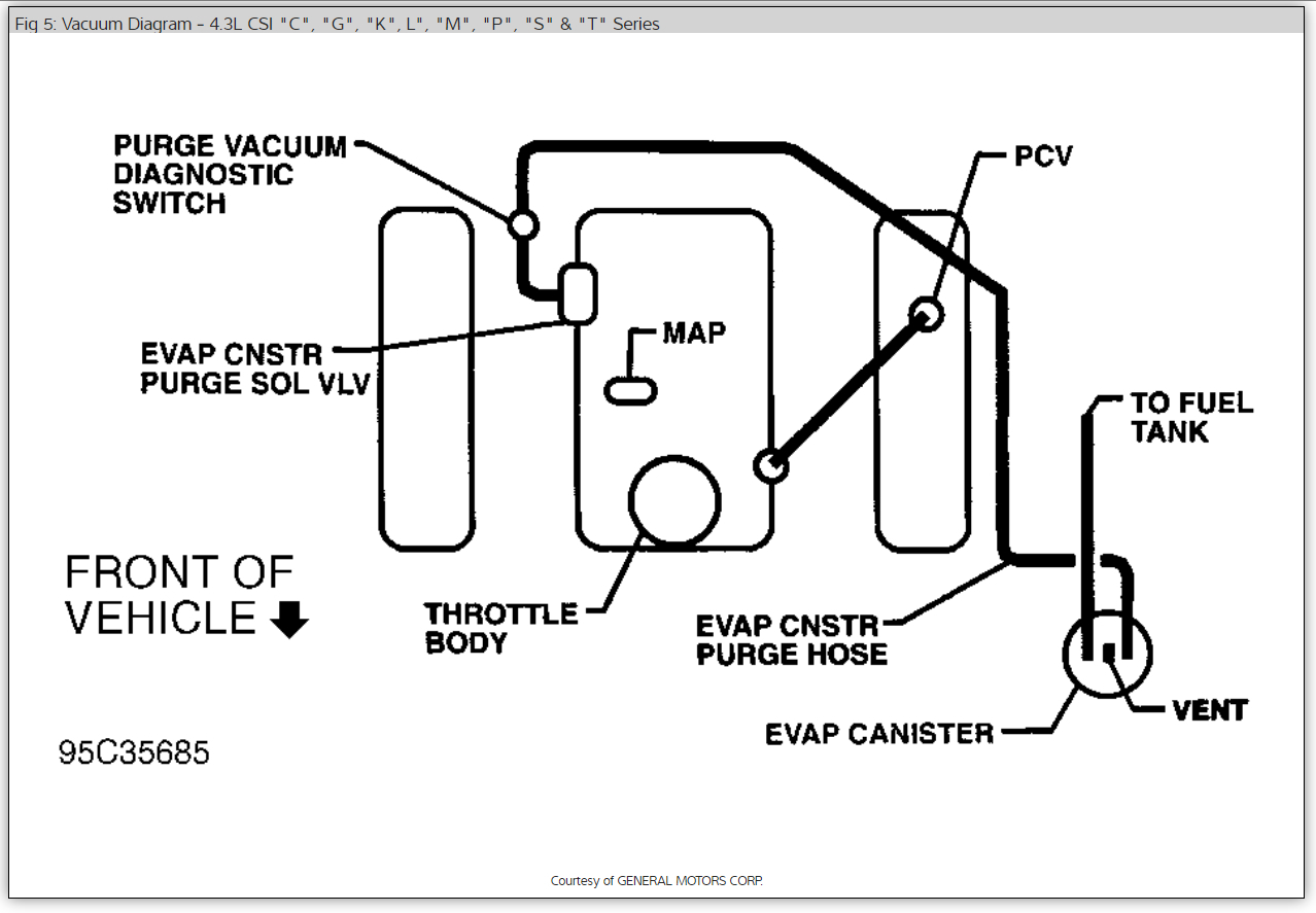
Repair Guides Vacuum Diagrams Vacuum Diagrams
Tools needed: Box Cutter- For removing old hoses.Side Cutters- For cutting new hose to length fast.Long Flathead Screwdriver- For the one of two pesky hoses that want to stay where they are.20ft: 5/32" vac hoseVacuum Tees. Skill Level: Intermediate (Hoses must not be mixed up) Top.

Repair Guides Vacuum Diagrams Vacuum Diagrams
The 2000 S10 vacuum hose diagram is a visual representation of the vacuum system in your vehicle. It shows the different hoses, valves, and connections that make up the system and how they are arranged. Each component is labeled with a specific code or abbreviation, making it easier to locate and identify them.

Vacuum Hose Diagrams 19942000 FWD Turbos
Vacuum functions as a fundamental dynamic air flow of the internal combustion engine. Without the proper vacuum and right setting of vacuum hoses, a car woul.

Vacuum Hose Diagrams 19942000 FWD Turbos
The term "vacuum hose" encompasses all the flexible tubes responsible for transmitting vacuum within a vehicle. However, you might hear "vacuum line" or "vacuum tubing" in reference to smaller diameter hoses. Common inner diameters for vacuum hoses include: 1/16″ (2mm) 3/32″ (3mm) 1/8″ (4mm) 5/16″ (8mm)

Repair Guides
The vacuum hose diagram is a visual representation of the various hoses that connect the engine components and control the flow of air and fuel. Significance of the Vacuum Hose Diagram: The vacuum hose diagram is essential for troubleshooting and maintaining your Saab 9-3's engine.
